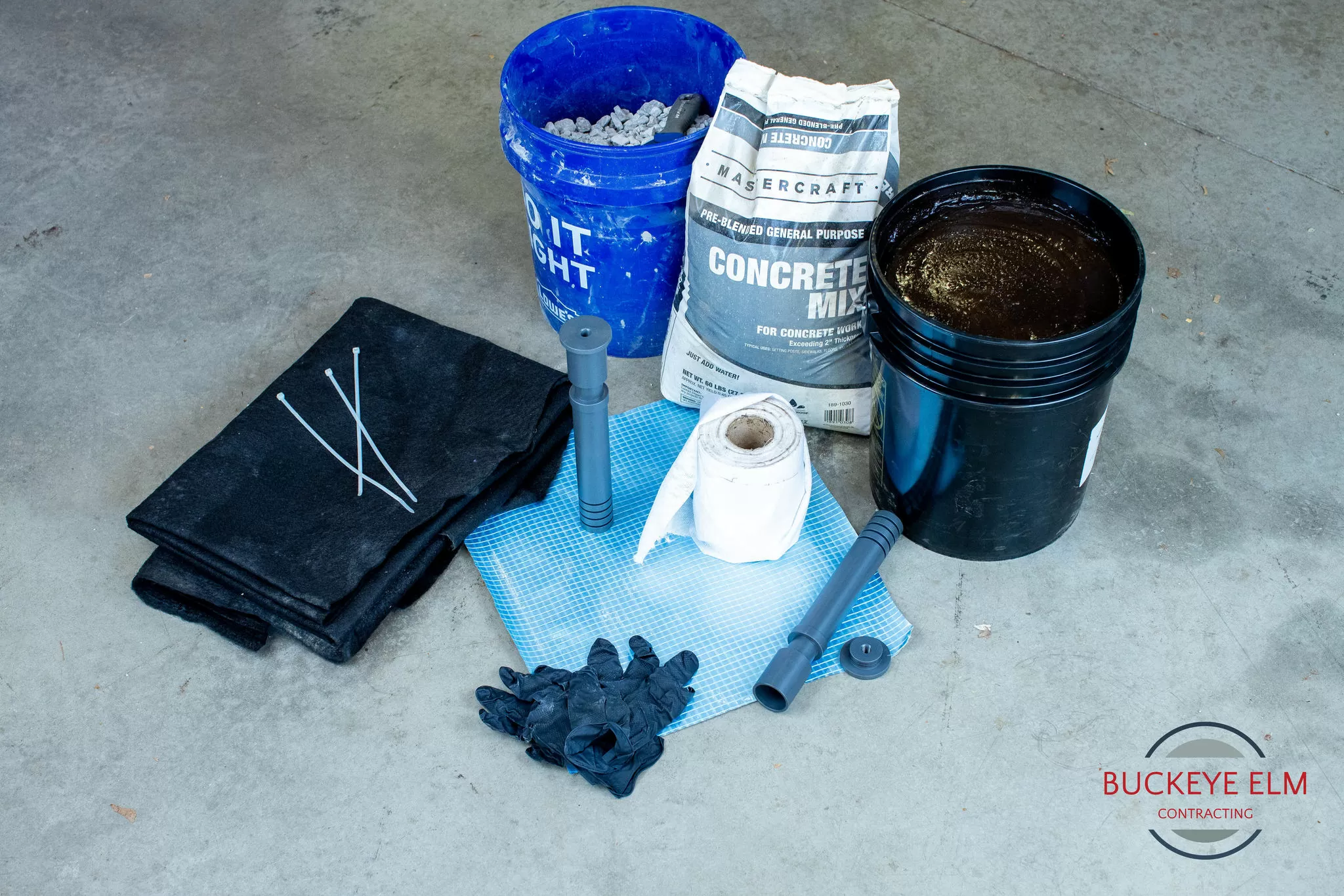
Equipment Needed
- Vapor Pin® Insert
- Vapor Pin® Insert Cap
- Hacksaw (optional)
- Power drill and small diameter bits (optional)
- ½” Diameter threaded rod (13 threads per inch)
- Dead blow hammer
Note: Not all items in the picture are on the list. The images are for example purposes, and you should contact the vendor of the barrier or coating about methods and materials used to marry the seal or coating to the Vapor Pin® Insert prior to proceeding to the field.
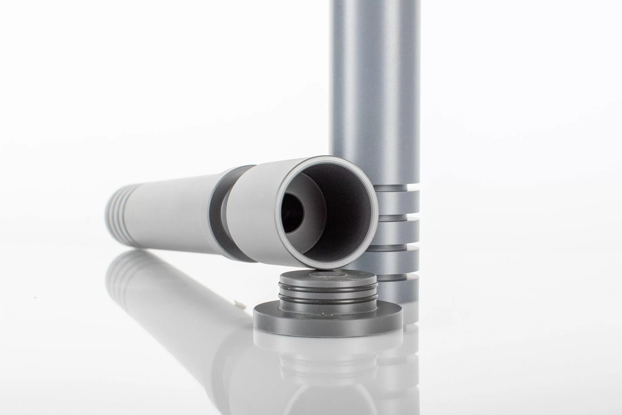
Step 1
Assemble the Vapor Pin® Insert and Cap by pressing the Vapor Pin® Insert Cap into the top of the Vapor Pin® Insert.
Step 2
You may shorten or extend your Vapor Pin® Insert to make sure that the base of the Insert will be below the barrier in the granular subgrade.
You can cut the insert with the hacksaw or use a schedule 40 PVC coupling with additional schedule 40 PVC pipe to extend the insert.
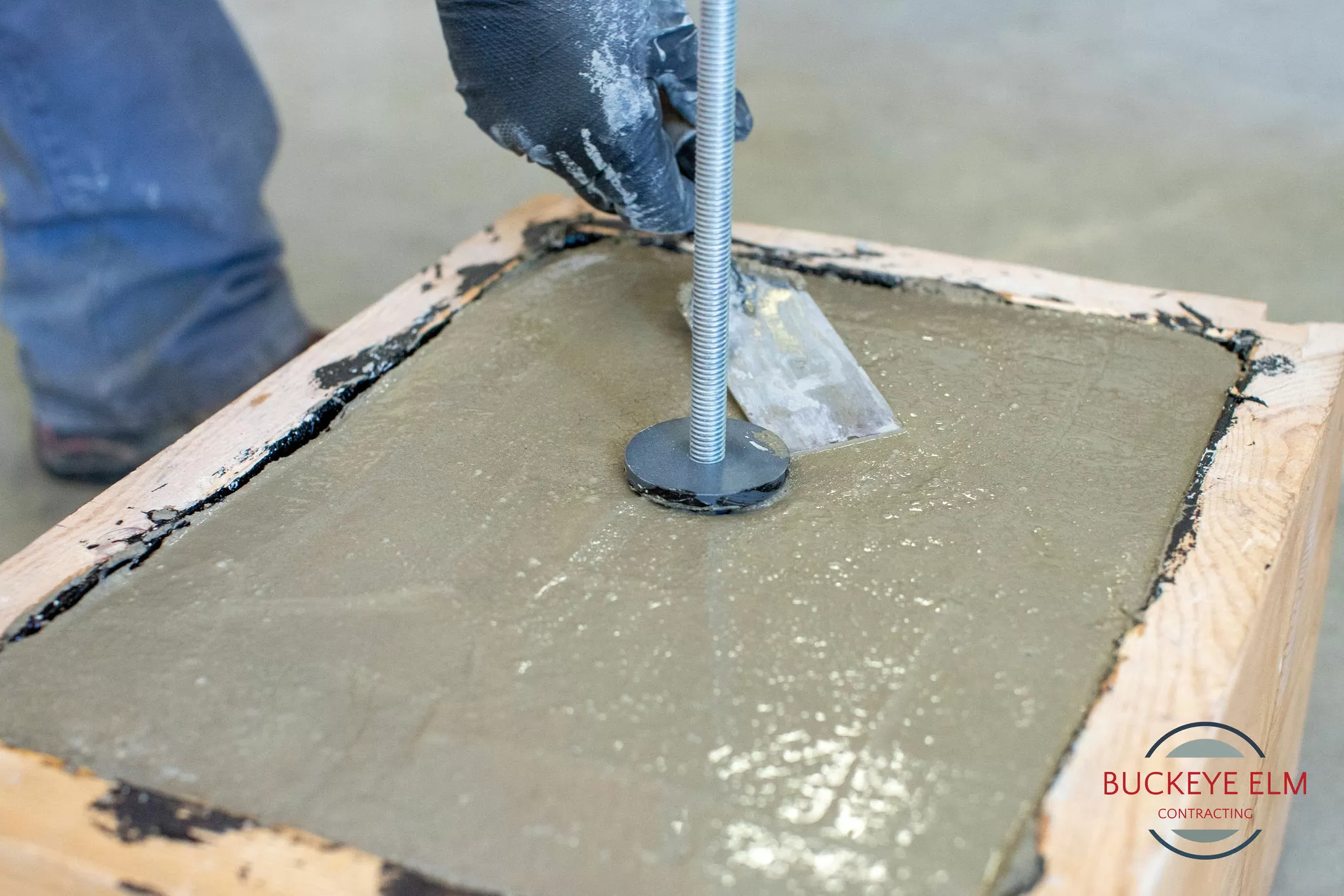
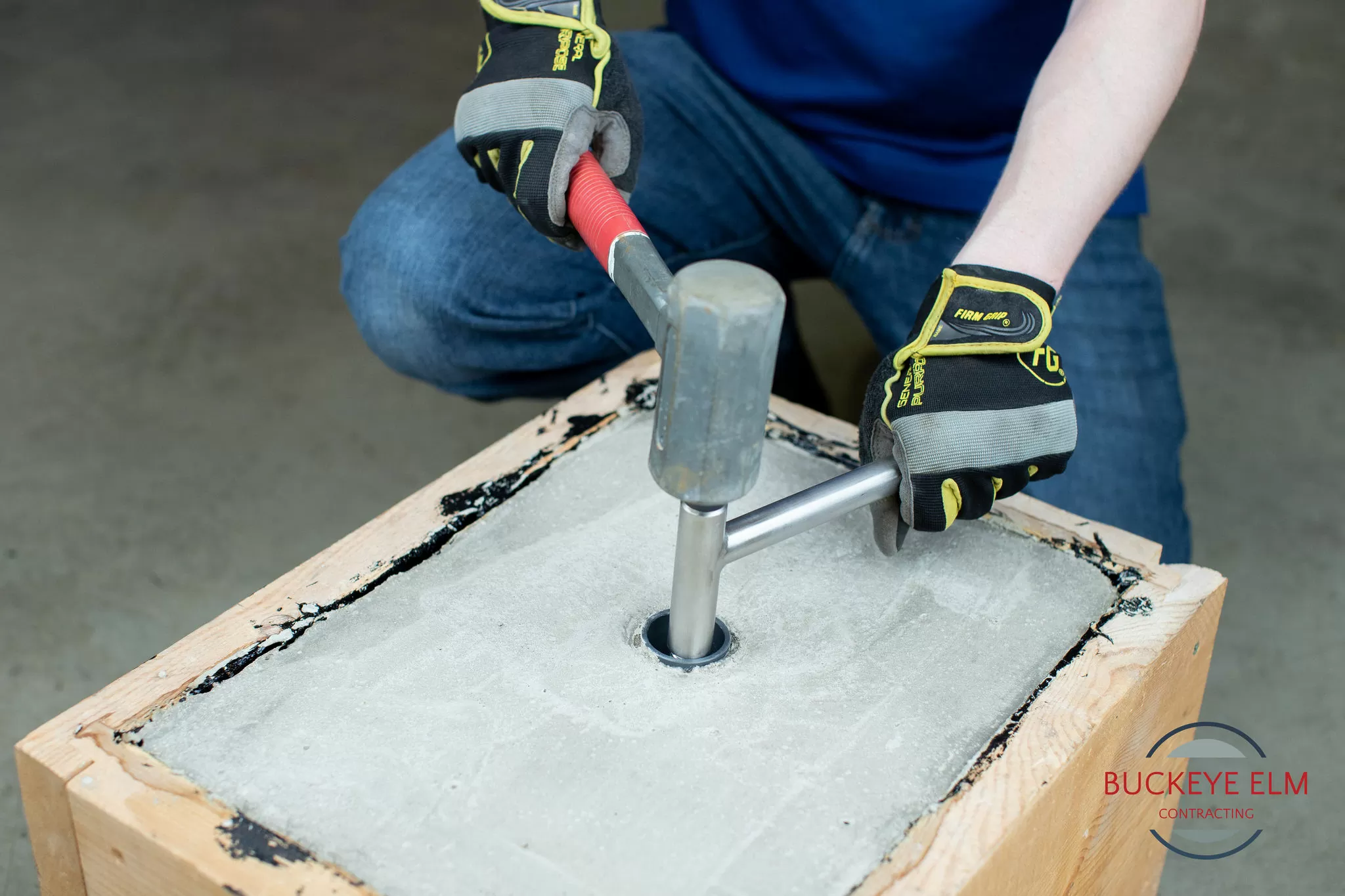
Use the dead blow hammer to set the threaded rod in the desired location of the Vapor Pin® Insert. The purpose of the threaded rod is to position the insert at the correct location and finished floor height.
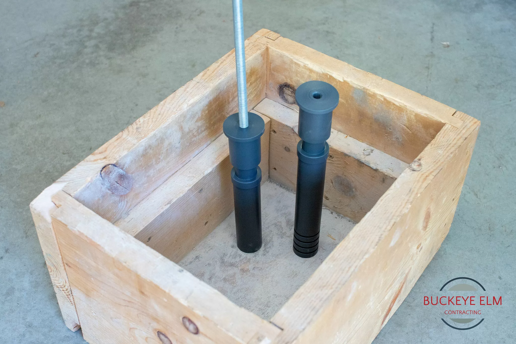
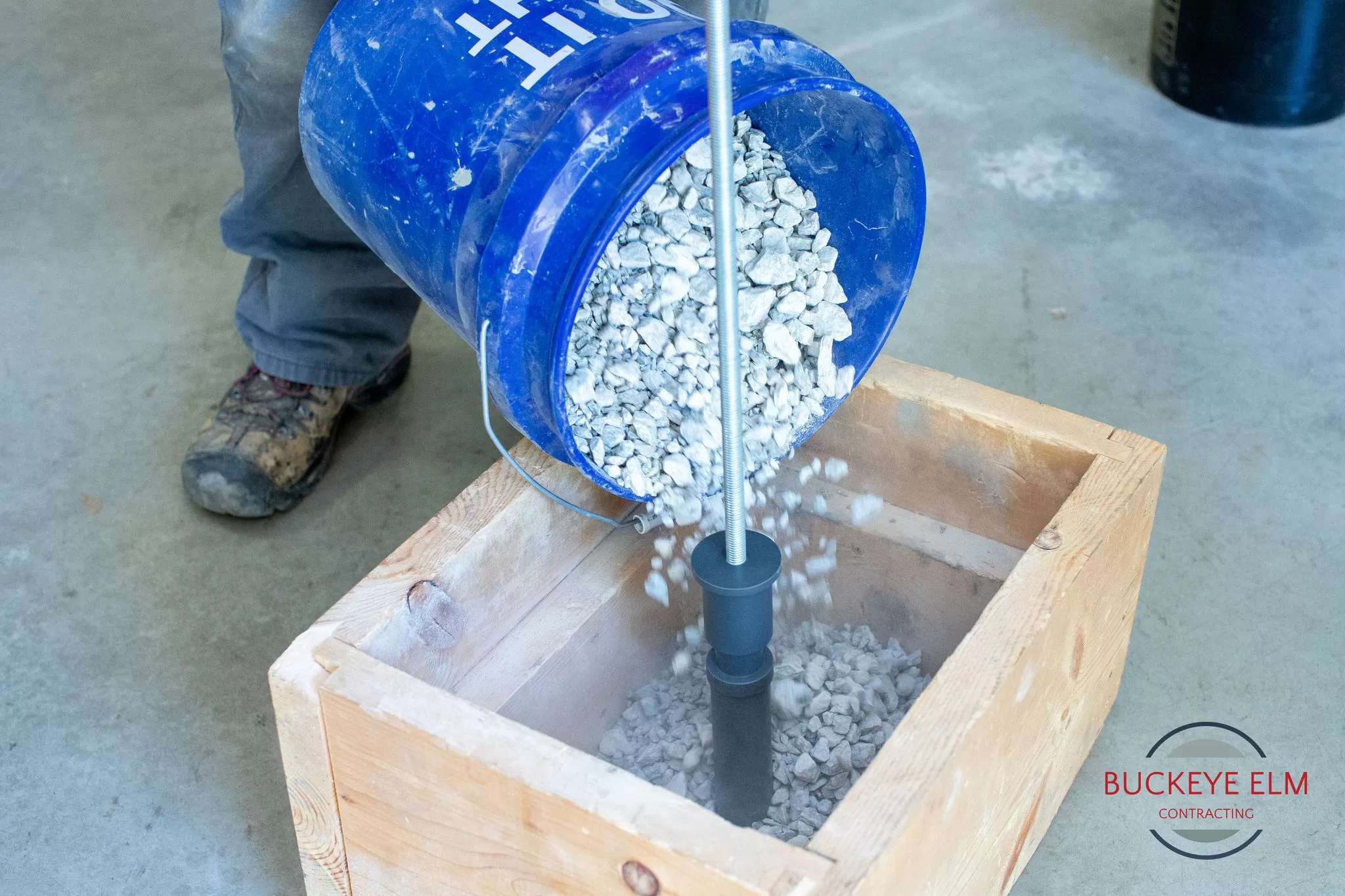
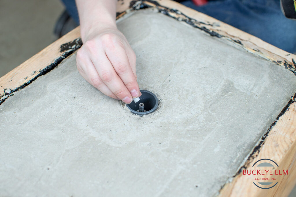
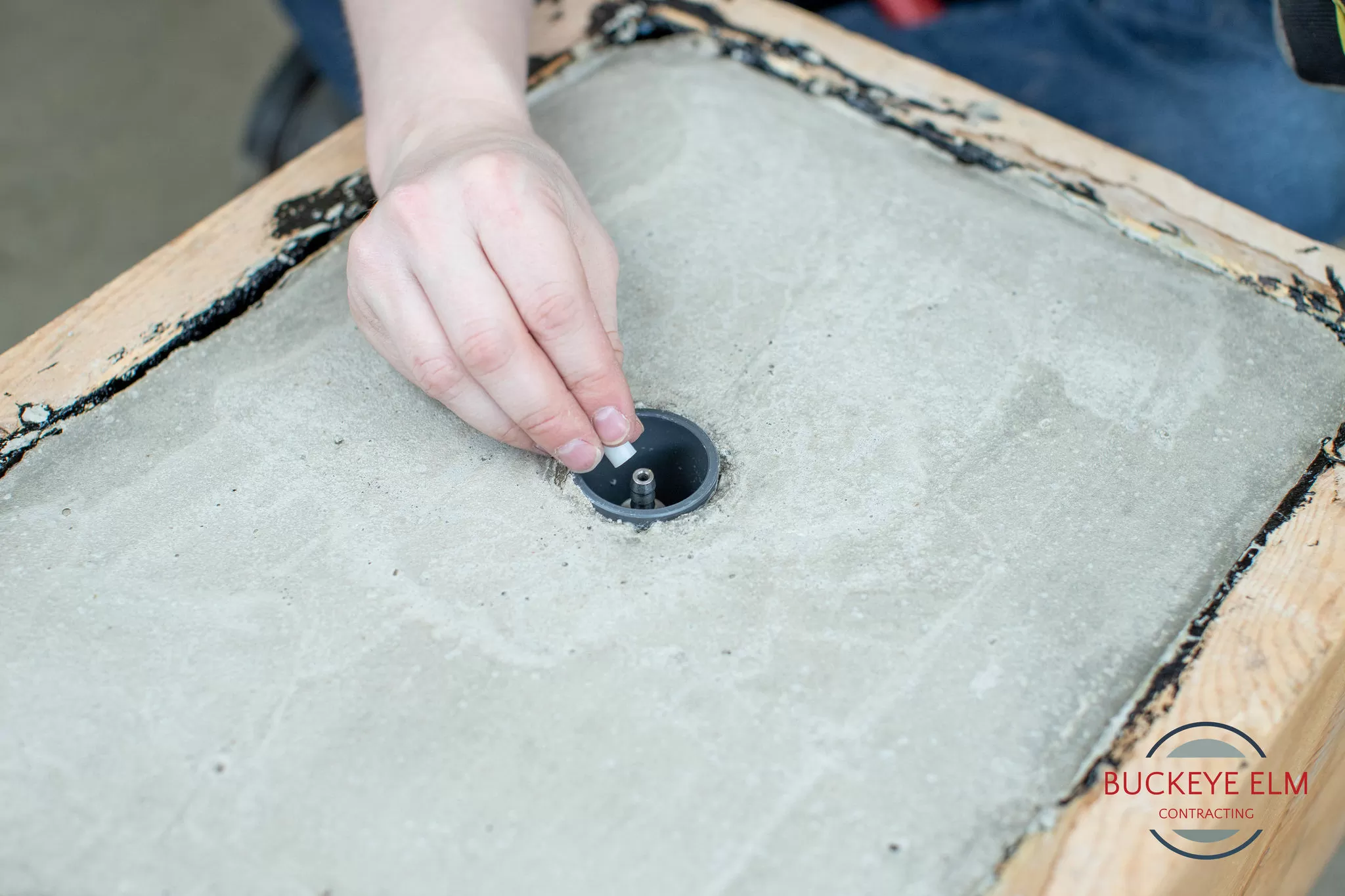
Step 3
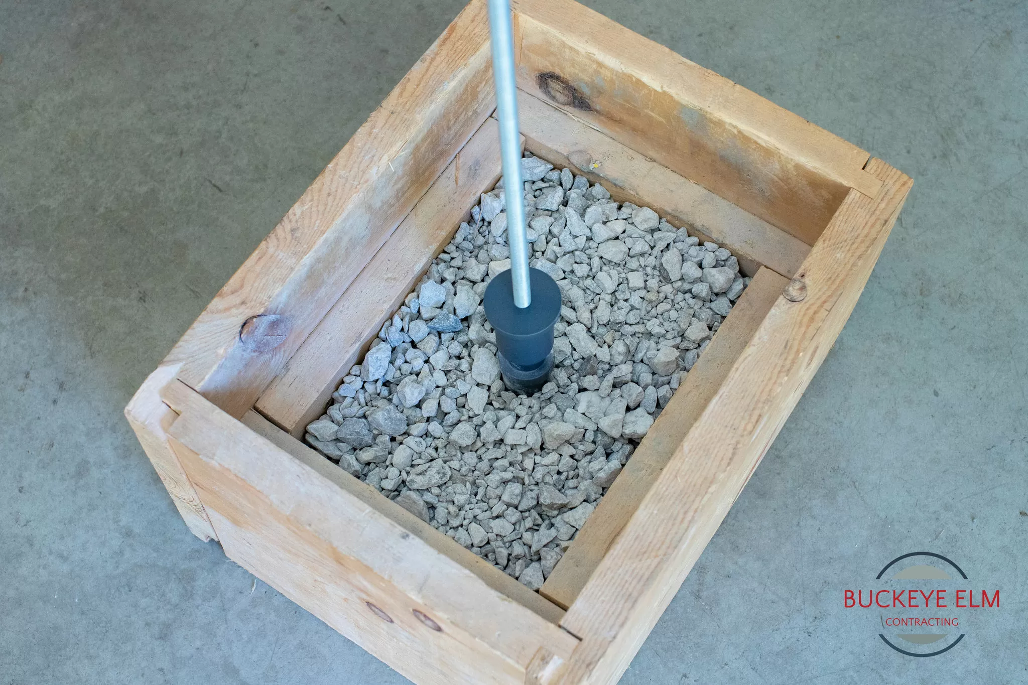
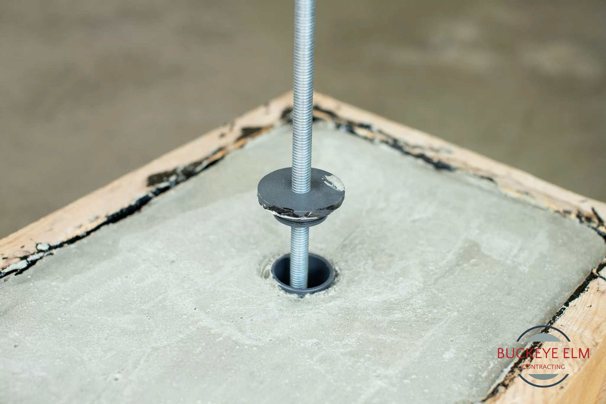
Fine tune the desired vertical position of the top of the Vapor Pin® Insert by rotating the insert on the threaded rod.
Make sure the bottom portion of the Vapor Pin® Insert is in the granular material beneath the future barrier.
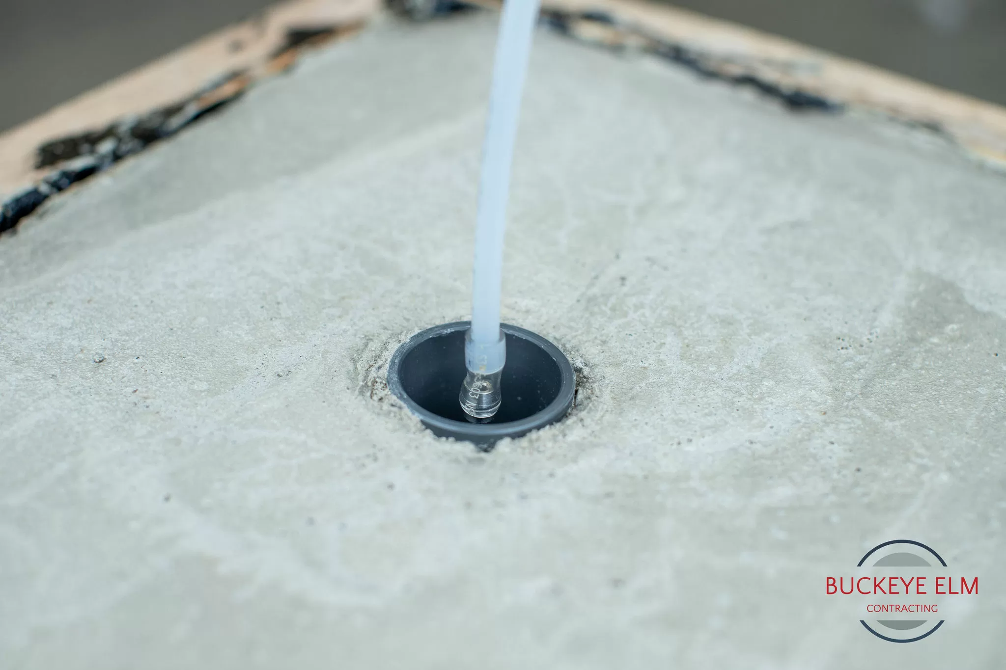
Step 4
Make sure the Vapor Pin® Insert is perpendicular to the proposed floor surface. Avoid bending the threaded rod, as it may inhibit its removal after the concrete has cured.
It is important that the position of the Vapor Pin® Insert be perpendicular to the slab so that the Vapor Pin® Secure Cover meets uniformly with the floor.
Step 5
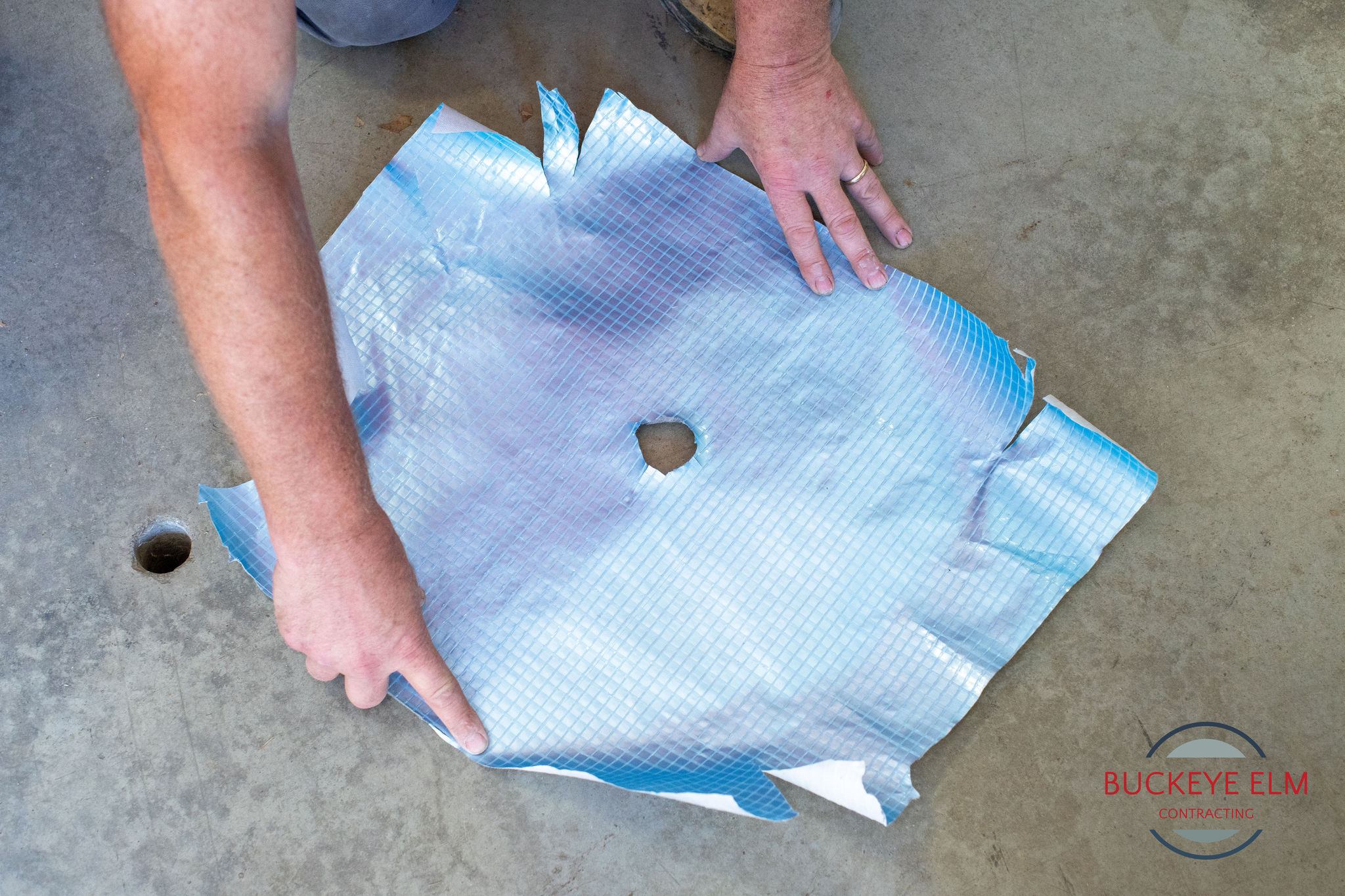
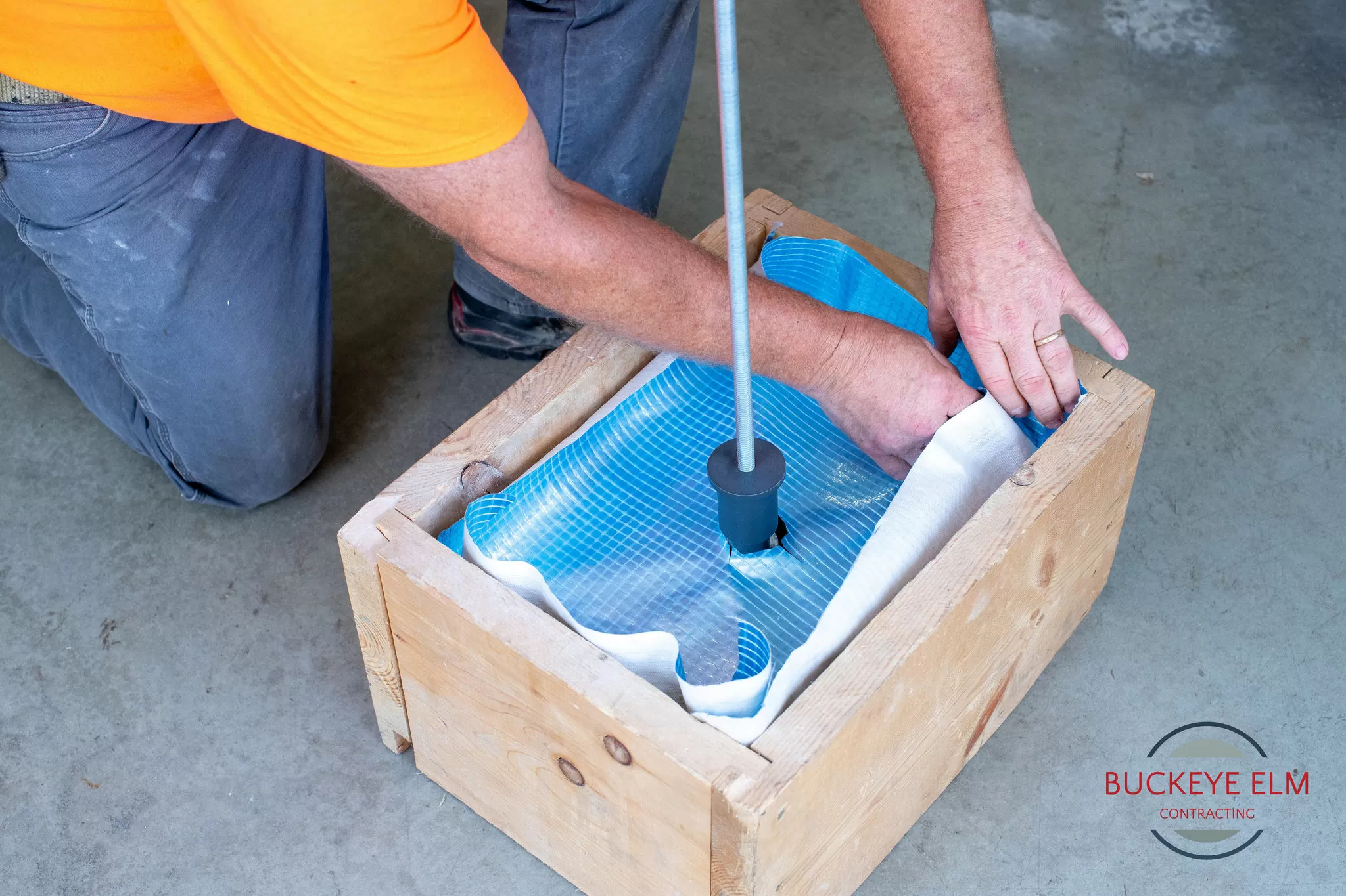
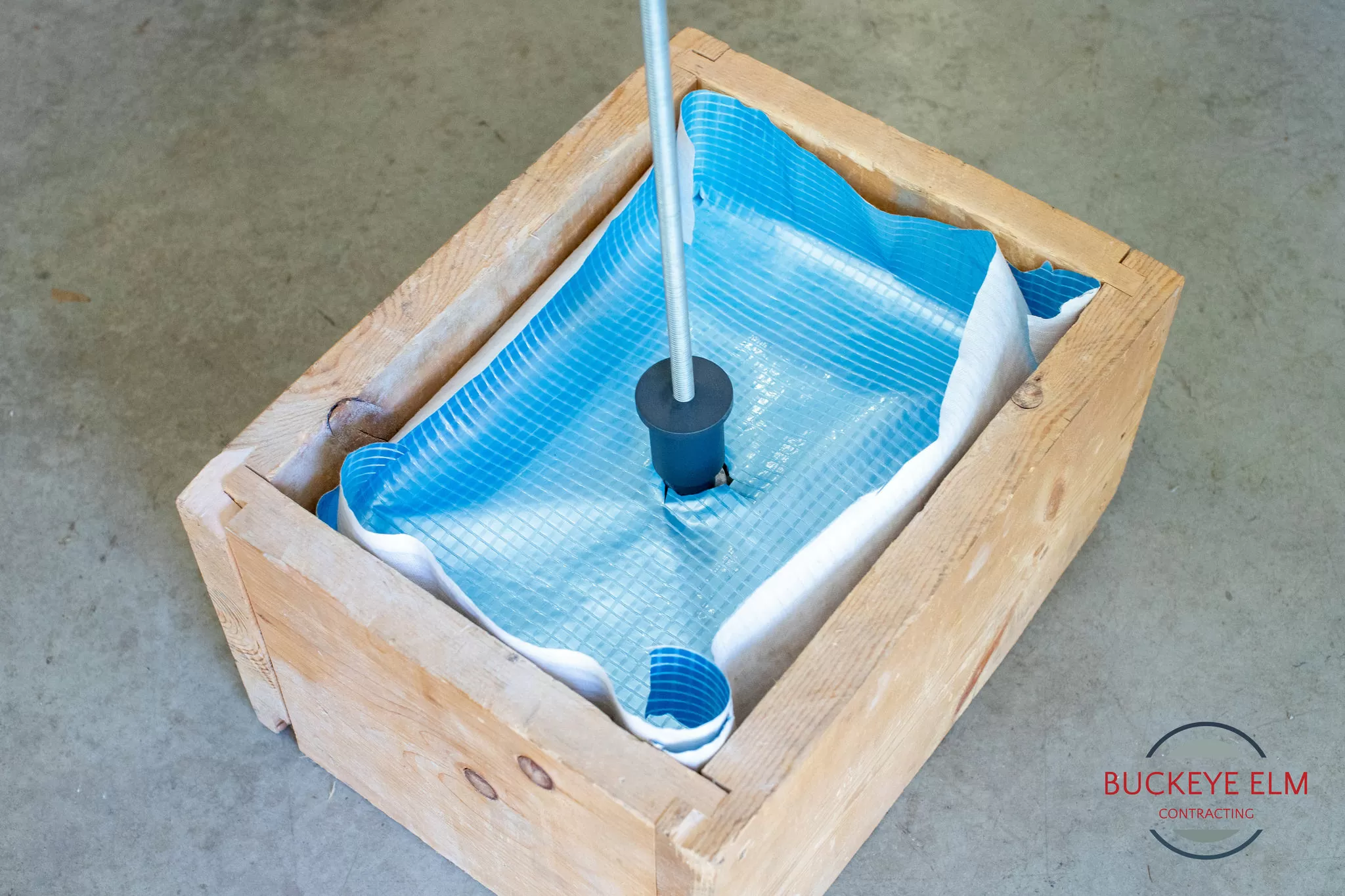
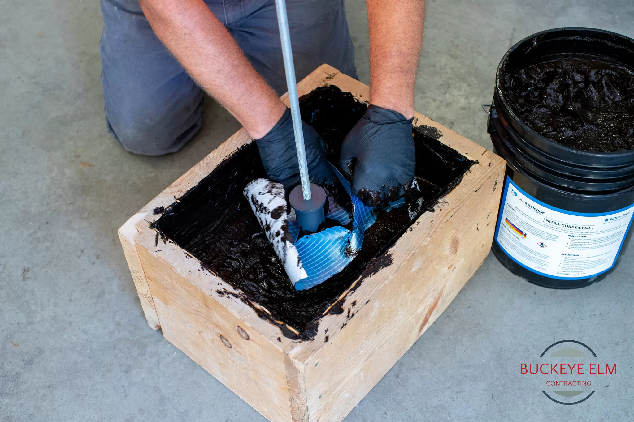
Slit or trim the barrier as it is placed around the Vapor Pin® Insert and make the necessary repairs to marry the barrier to the insert.
You may also pre-cut pieces of vapor barrier as seen in the images.
Step 6 (a)
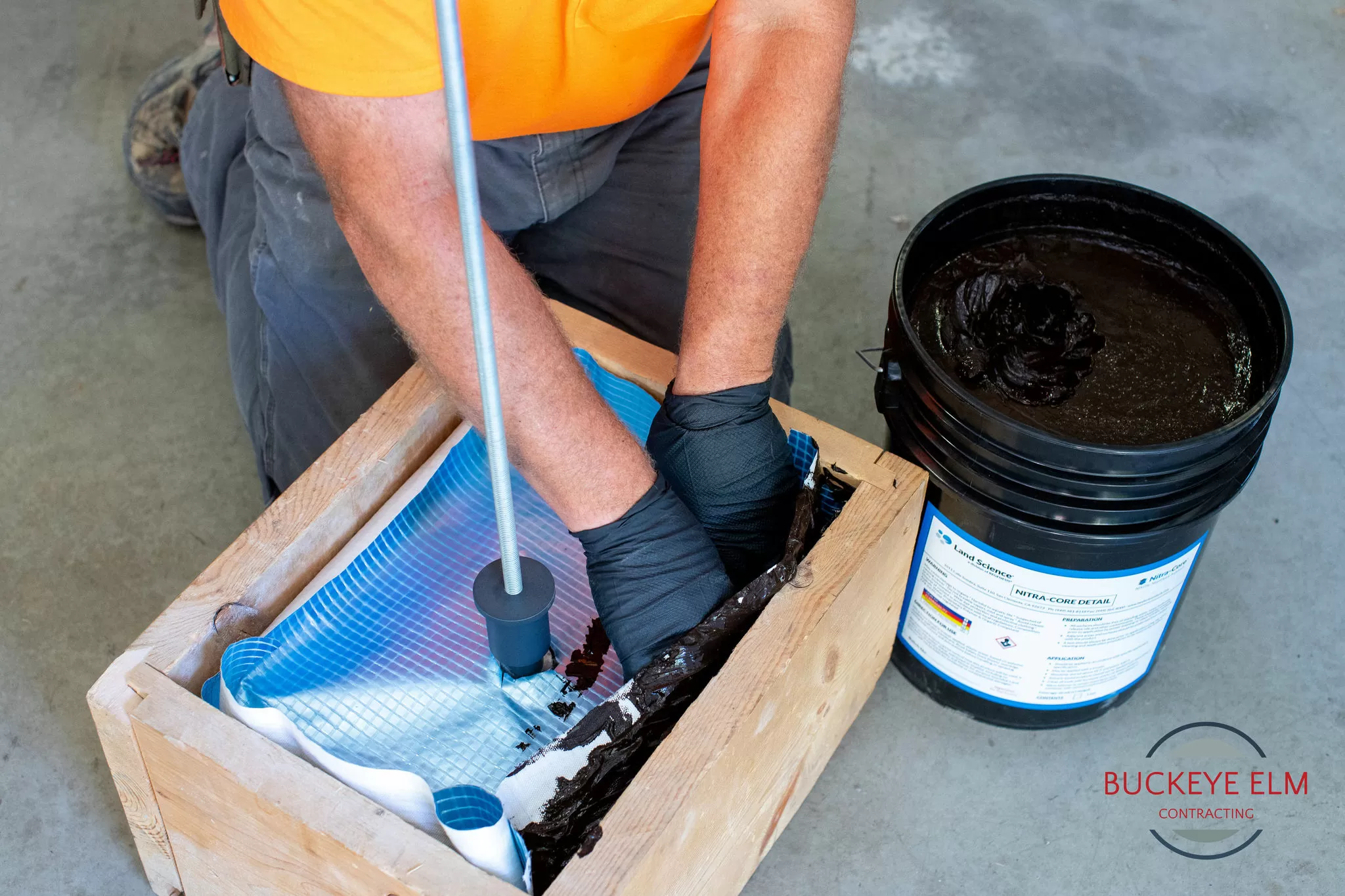
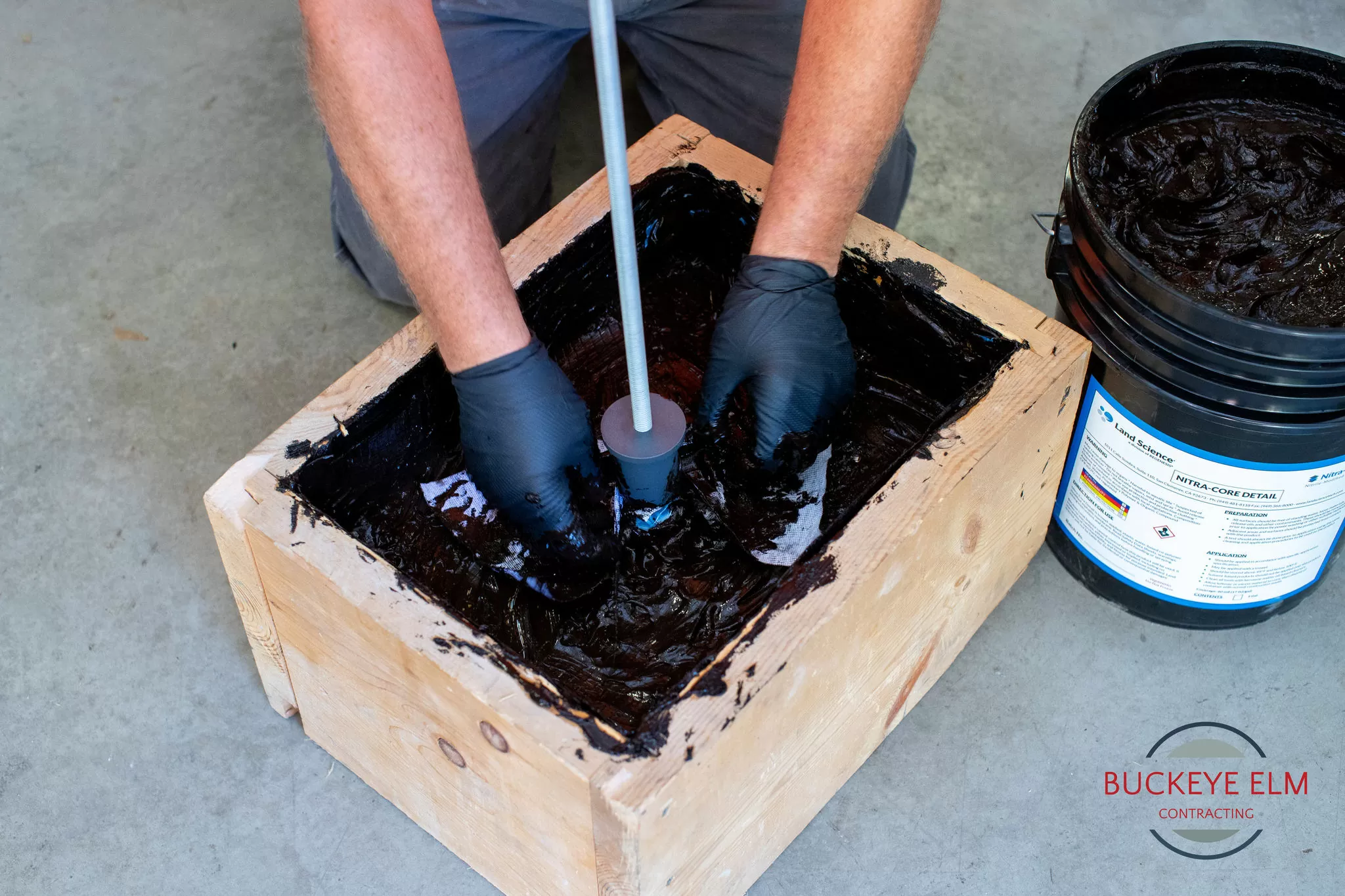
Marry the barrier to the Vapor Pin® Insert per the barrier manufacture’s specification prior to pouring the concrete clab.
In the example below, the vapor barrier material is being covered with a sealant to provide a mating surface for a more precisely cut piece of vapor barrier material.
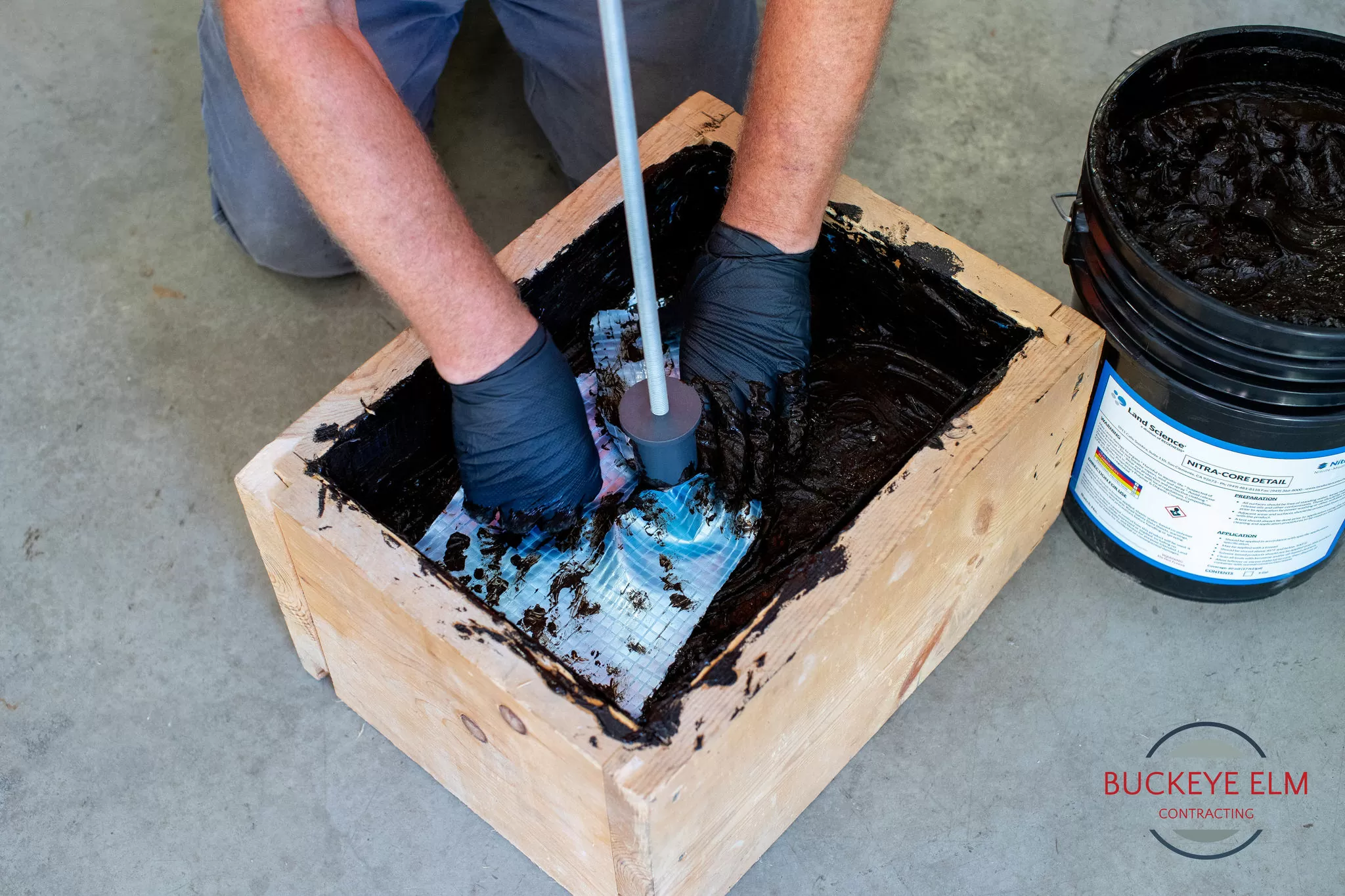
Step 6 (b)
Cut a piece a piece of vapor barrier material larger than the hole in the already placed material
This piece should have a hole/slits within it to precisely match the Vapor Pin® Insert
A plastic tie strap is then placed around the Vapor Pin® Insert and patching piece to provide a tighter seal.
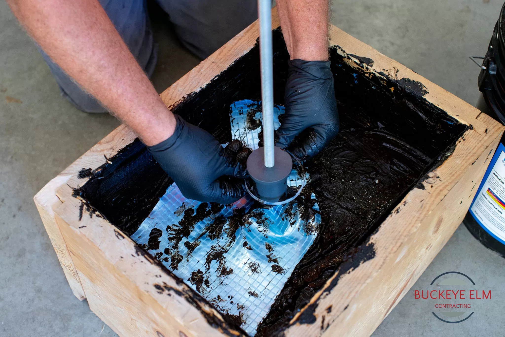
Step 6 (c)
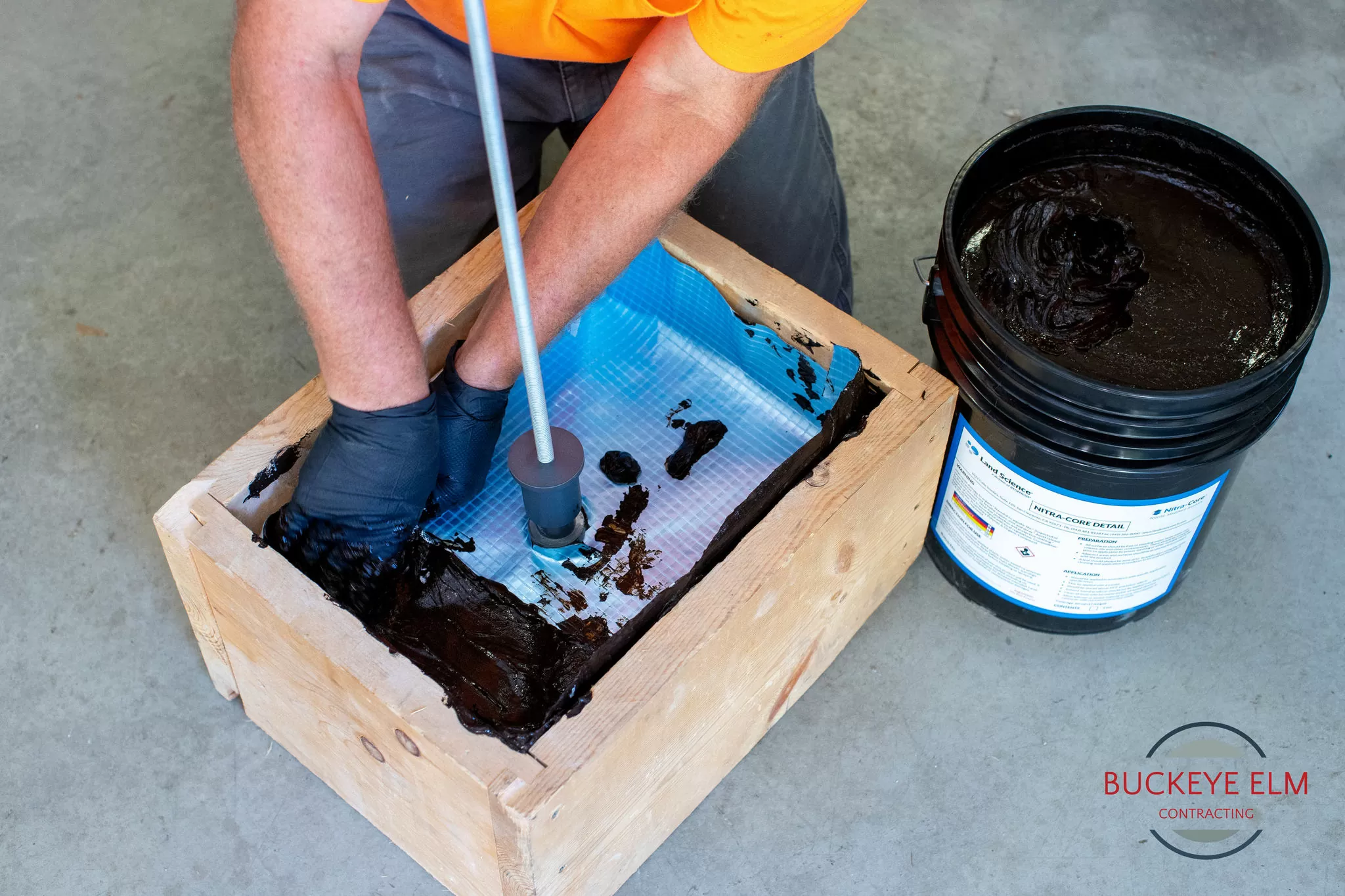
Seal around the Vapor Pin insert with liquid sealant designed for the vapor barrier material
Bonding material similar to geotextile cloth is used to provide structure to the liquid sealant.
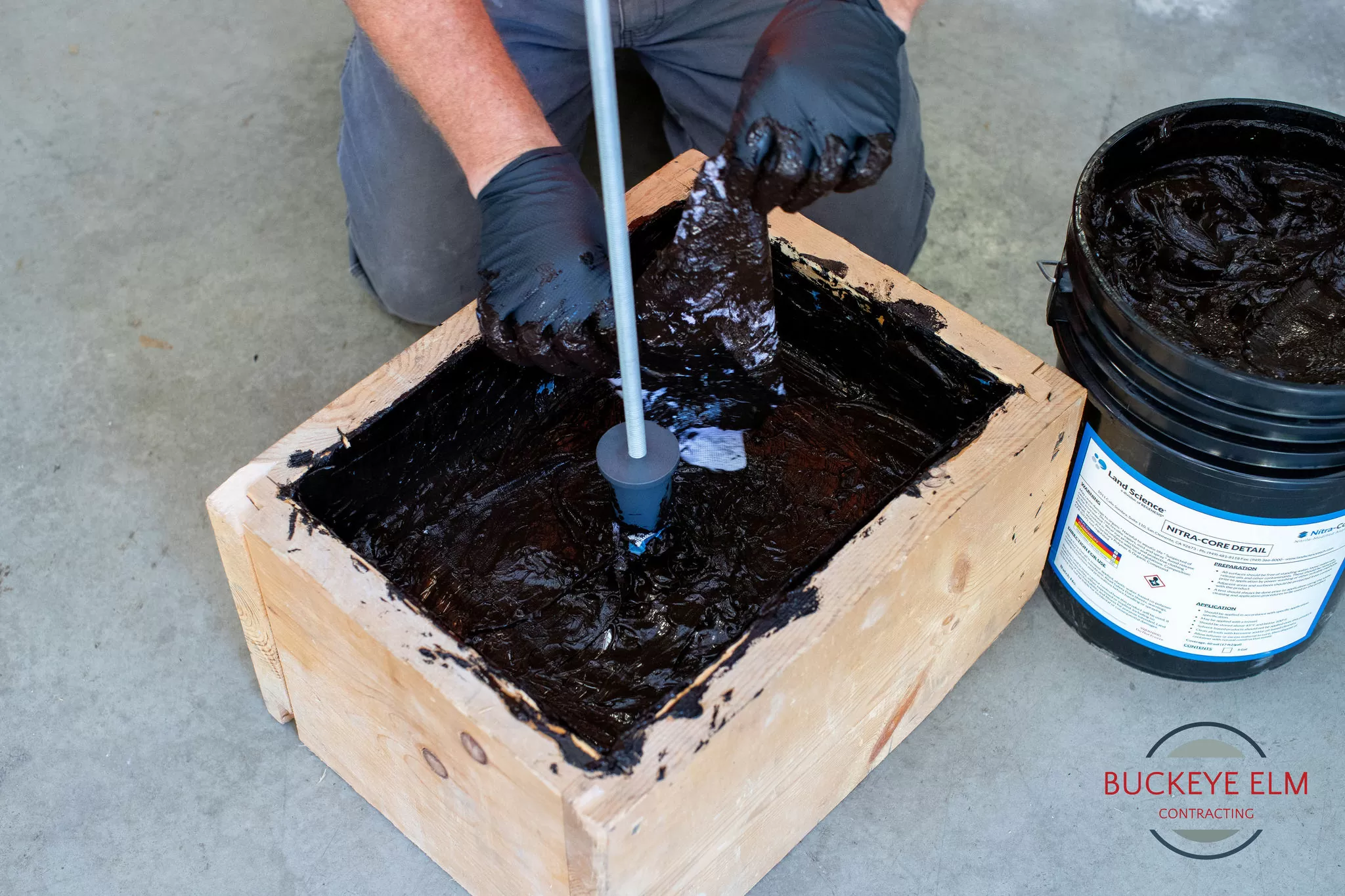
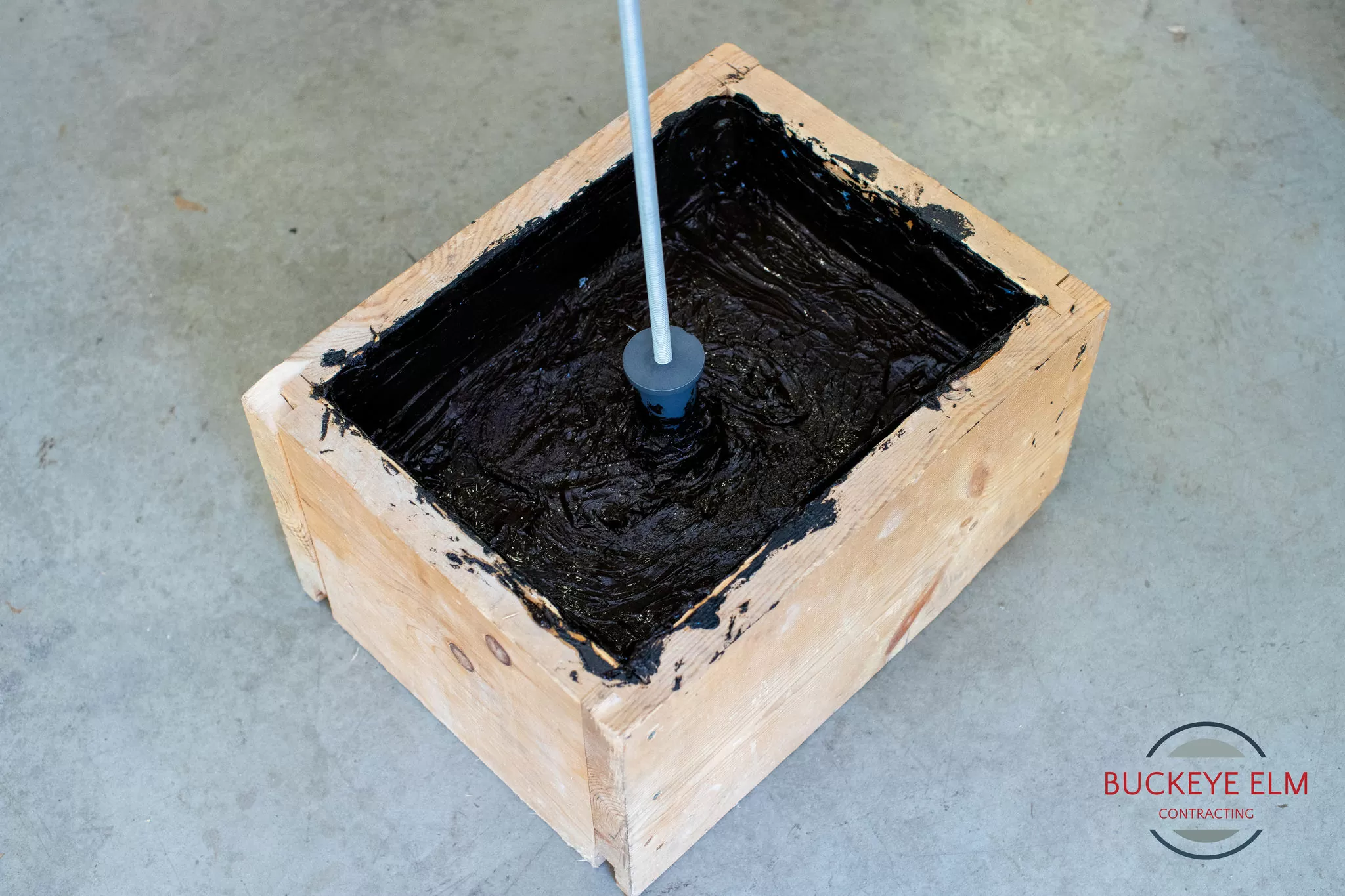
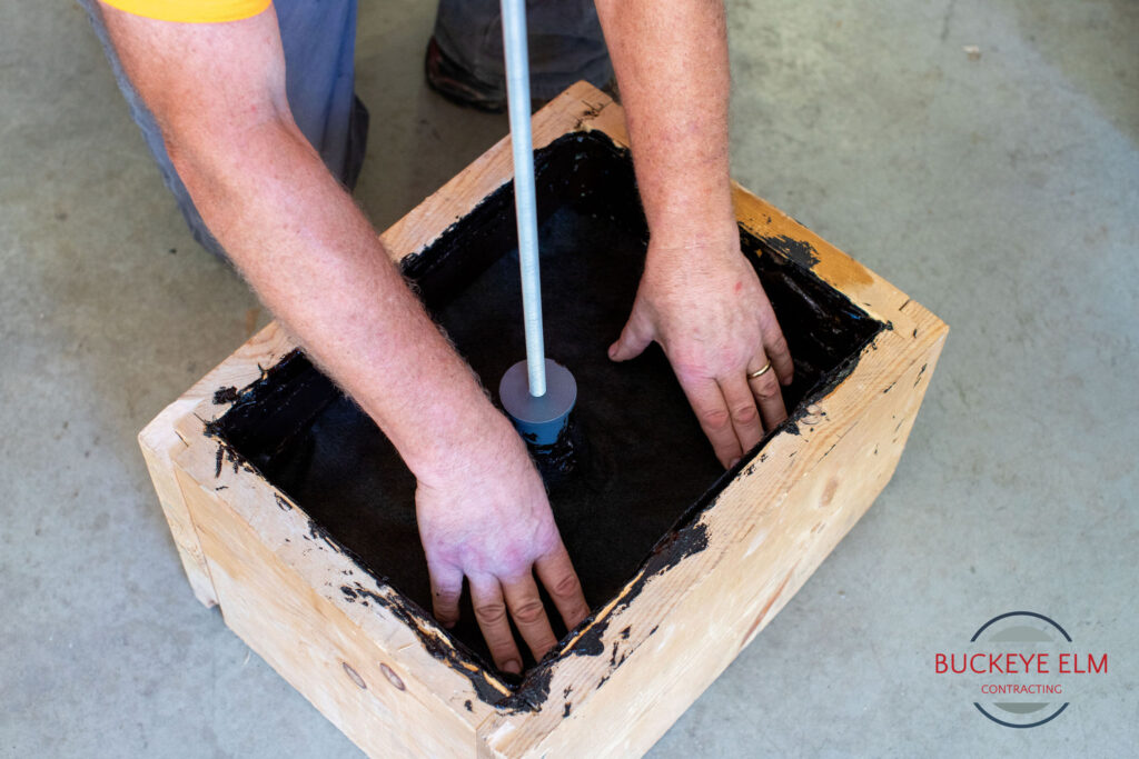
Step 6 (d)
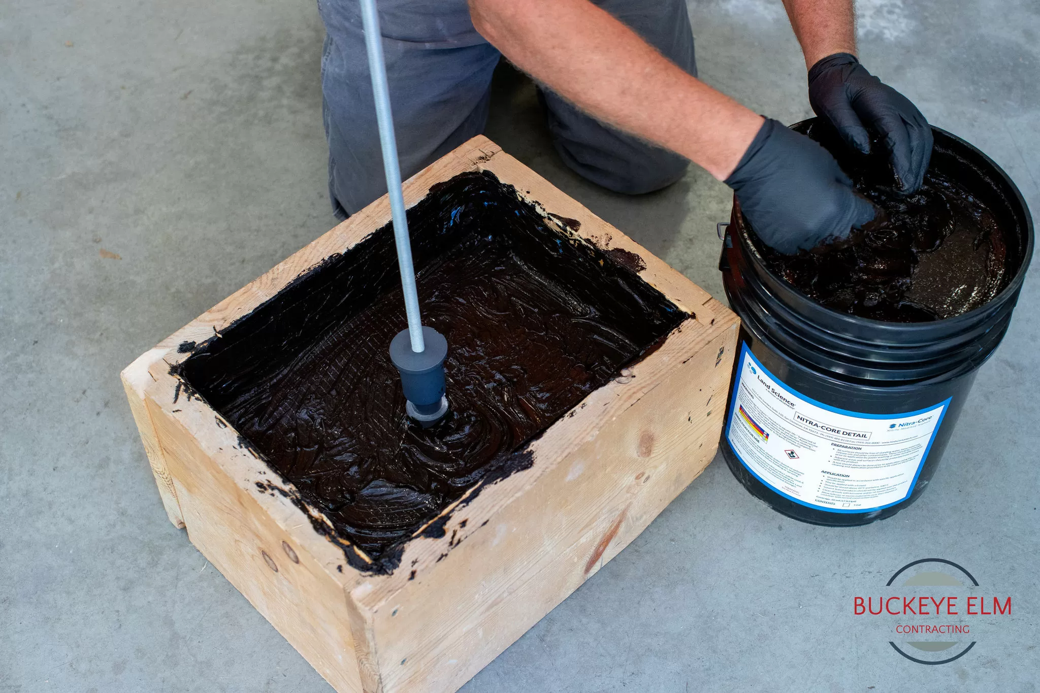
A black bonding fabric / protective material is applied over the liquid sealant prior to the concrete pour.
Step 6 (e)
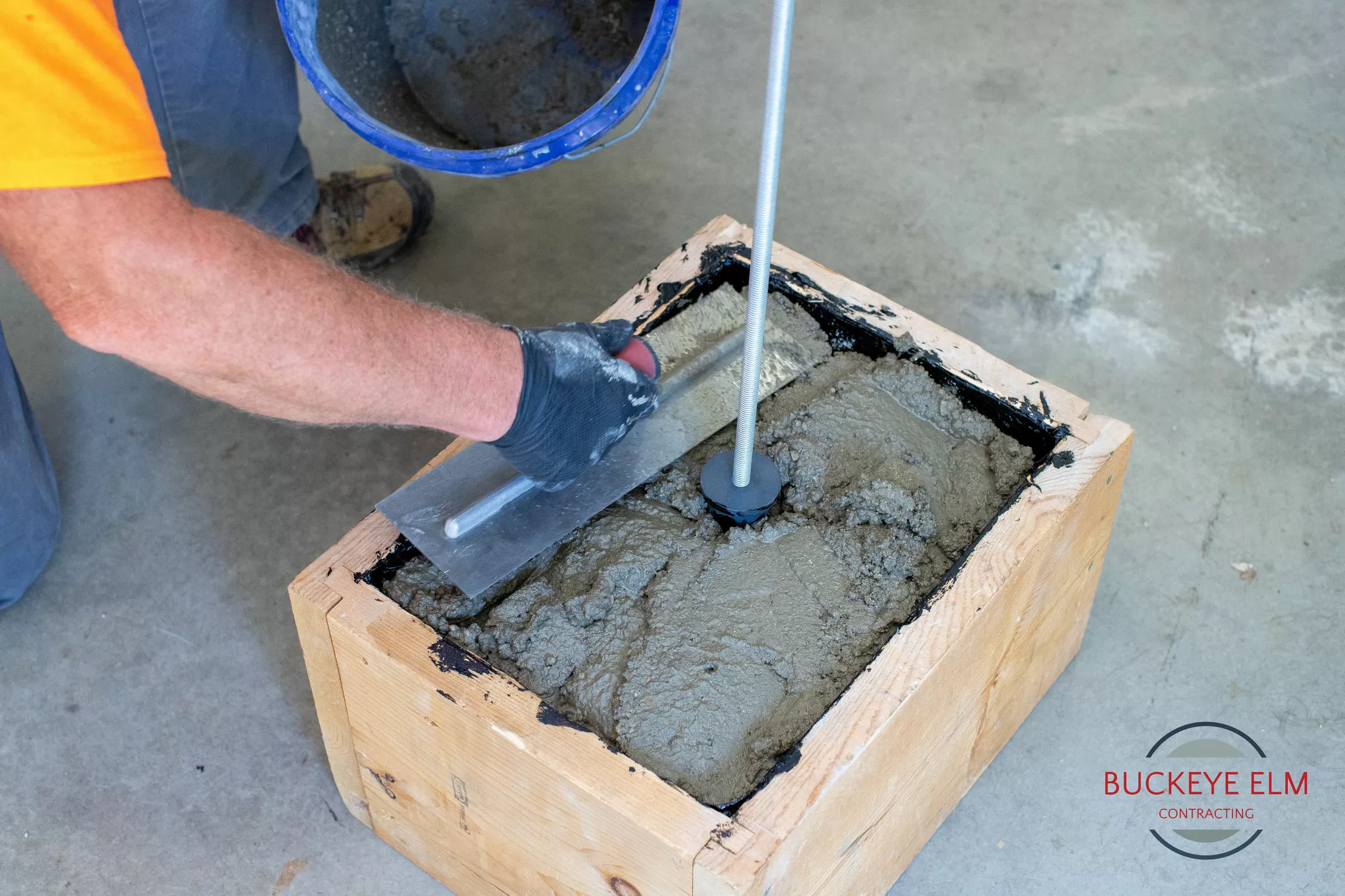
You may install the Insert to have the Cover of the Insert flushed on top of the concrete or flushed with the concrete. This is so that you may have a countersink installation of your Vapor Pin® Sampling Device if you would like.
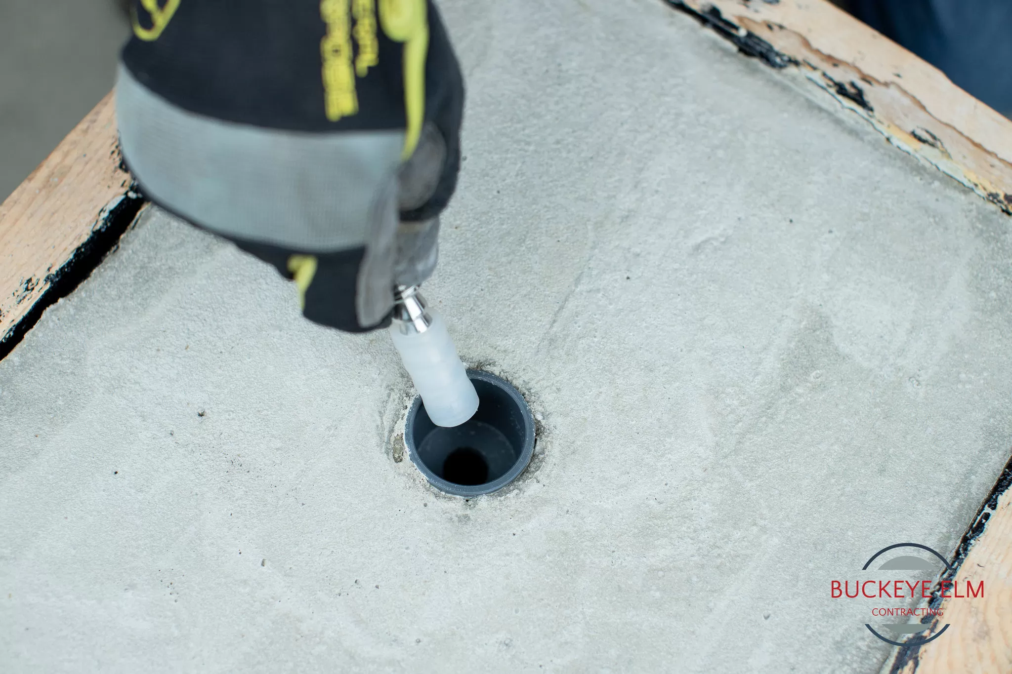
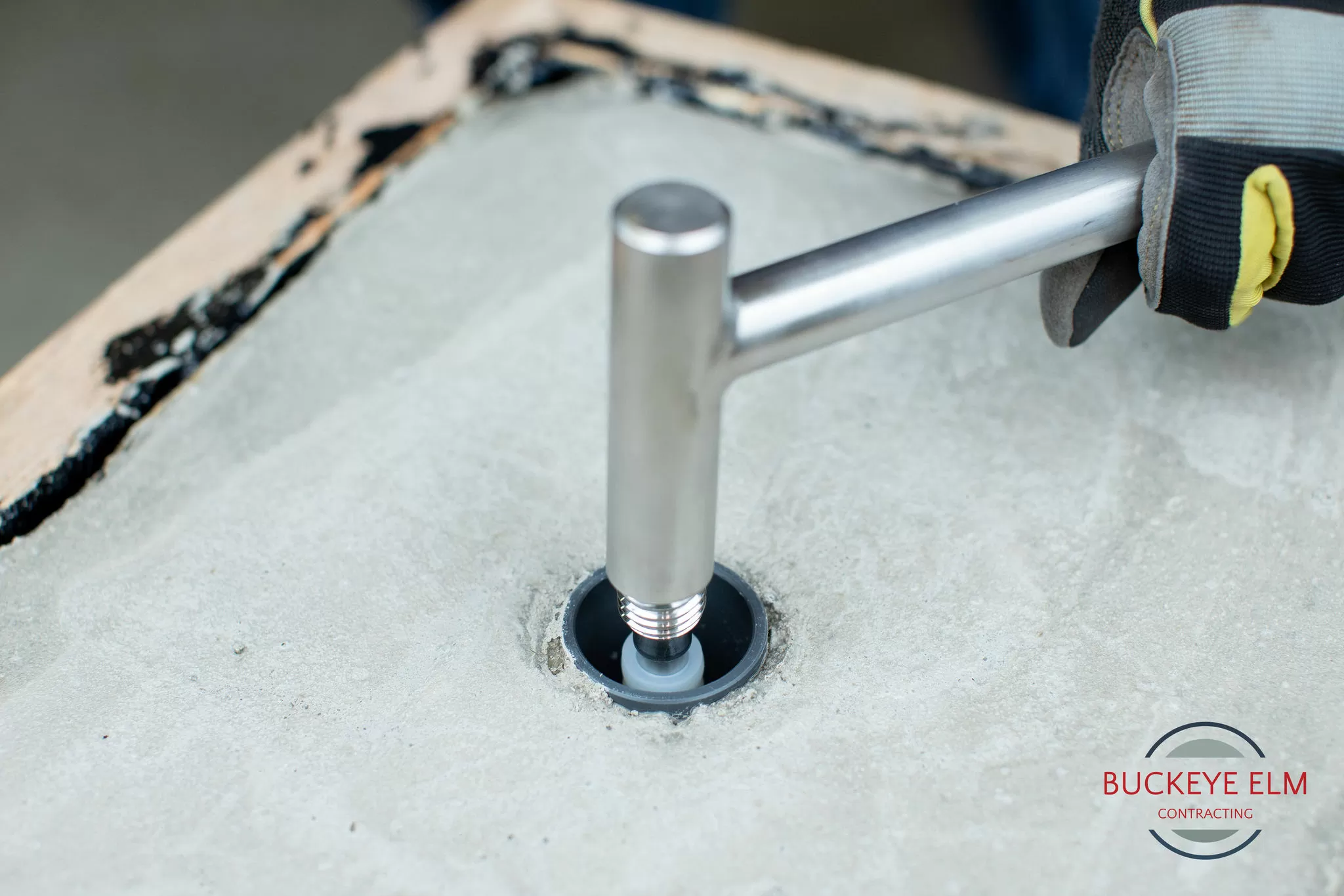
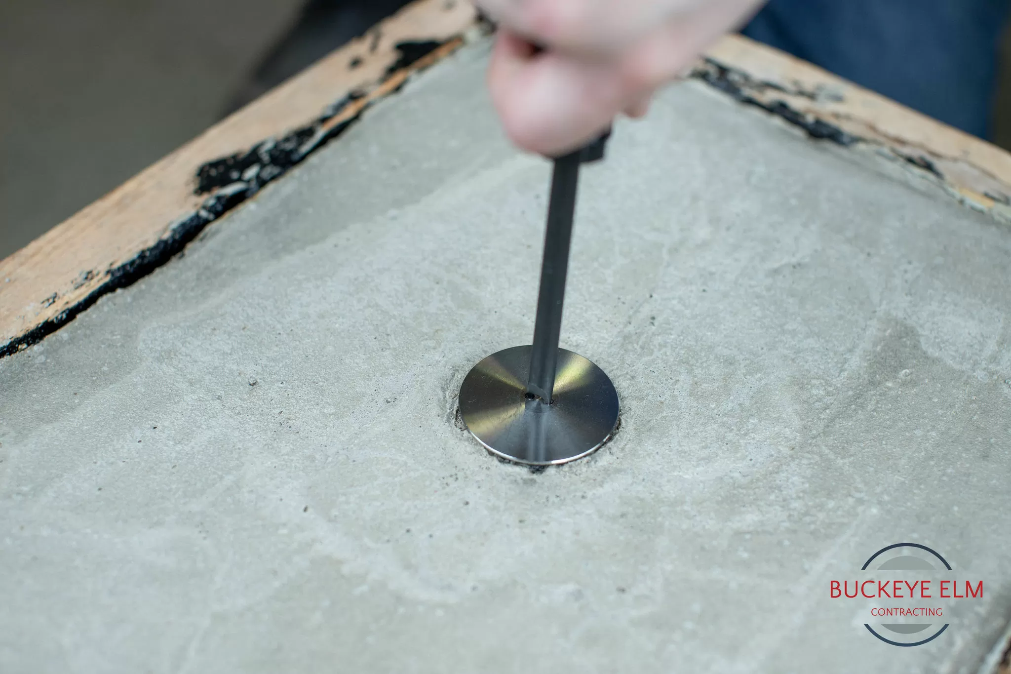
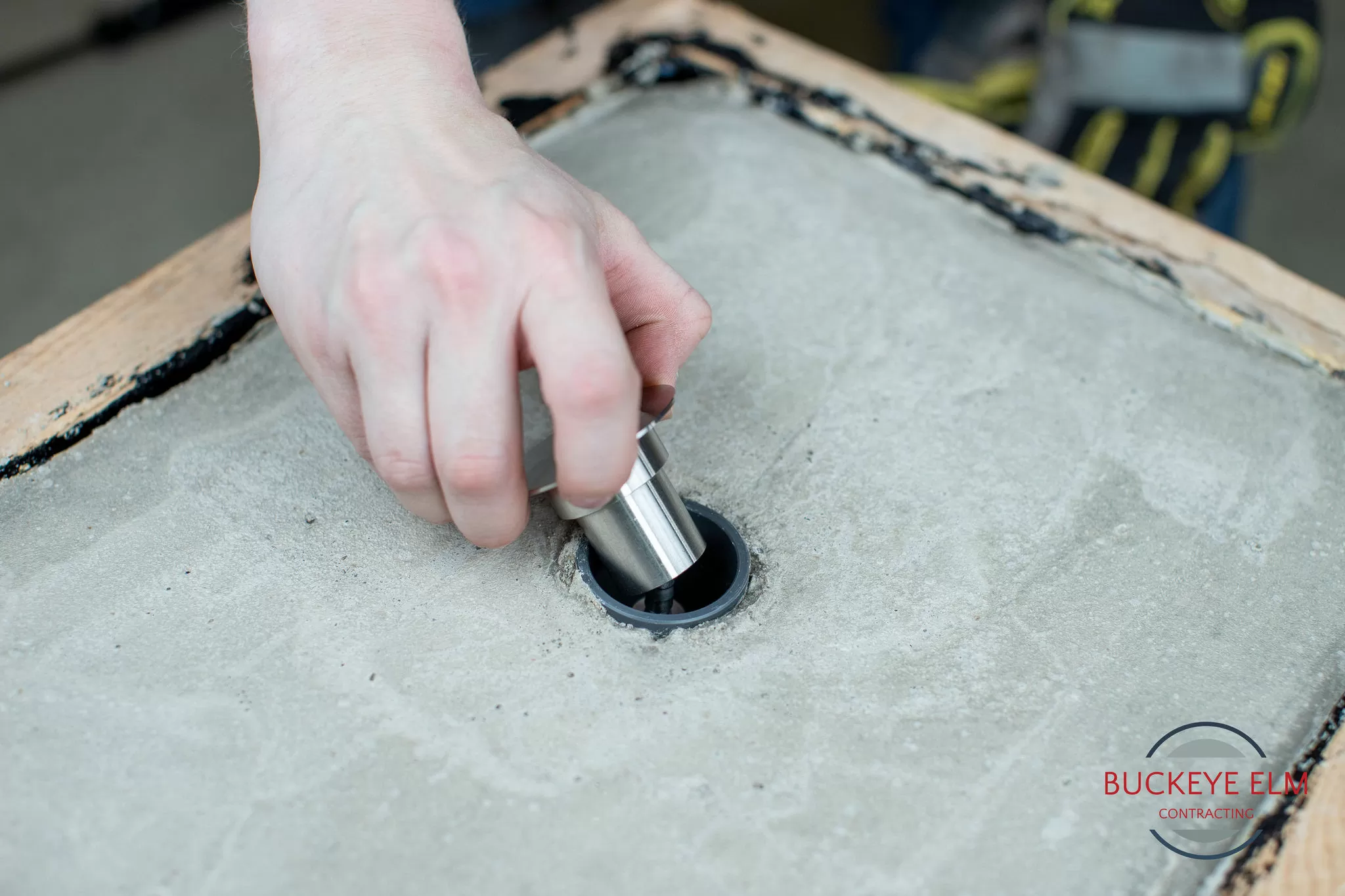
Step 7 (a)
Take your Assembled Vapor Pin® Sampling Device and put the end of it in your pre-made hole.
Start Hammering, with a dead blow hammer, your Vapor Pin® in by using the Installation/Extraction Tool.
Step 7 (b)
Once installed, purge your air and apply your Vapor Pin® Cap.
Note: It’s normal to see the Vapor Pin® Sleeve Ride up and buldge slightly over and below the threads of the Vapor Pin®.
Step 7 (c)
Once the Vapor Pin® has been idle long enough post purging of air, per your state’s regulations, you may sample from your sample port.
We recommend using Tygon Connectors as the connection point between the Vapor Pin® Sampling Device and your preferred stiff tubing.
Once sampling event is over, reapply your Vapor Pin® Cap and install your Stainless-Steel Secure Cover by screwing it on to the Vapor Pin® Sampling Devices threads.
Step 7 (d)
Once installed, purge your air and apply your Vapor Pin® Cap.
Note: It’s normal to see the Vapor Pin® Sleeve Ride up and buldge slightly over and below the threads of the Vapor Pin®.